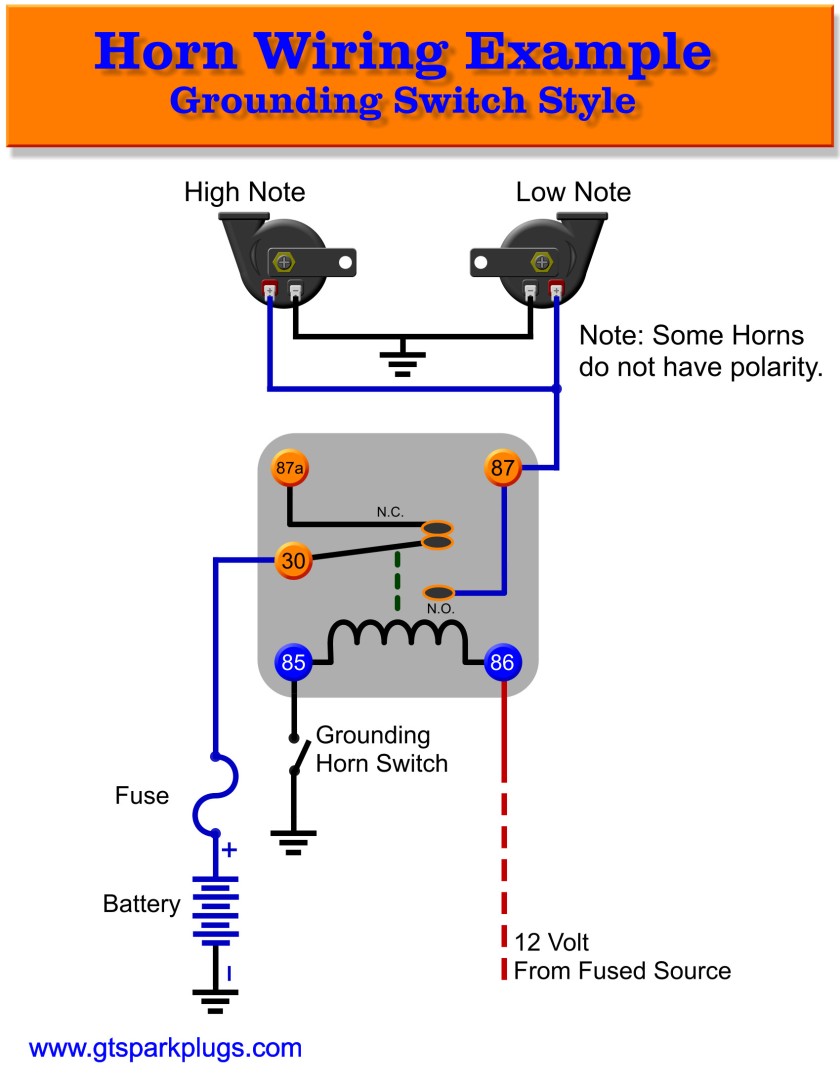
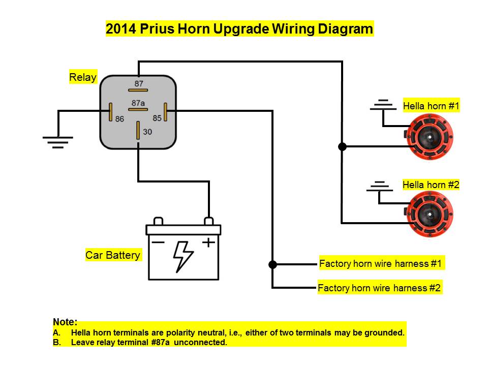
Circuit Diagram Of Electric Horn
electronic horn circuit.
this simple circuit helps to make louder horn for vehicle or alarm this circuit constructed by two timer ic555 and the output unquestionable produced through 8 immense speaker circuit diagram for electronic horn circuit construction and full of zip here first timer ic produce pulse output and second timer ic manufacture build high frequency pulse then the output from the second timer ic fed to the immense speaker the.
kleinn air horn wiring diagram find not guilty wiring diagram.
10 2 2020 assortment of kleinn air horn wiring diagram a wiring diagram is a streamlined acknowledged pictorial representation of an electric circuit it shows the components of the circuit as streamlined forms and afterward the power and signal associates links in the midst of the tools.images of wiring diagram for horn relay harley davidson a new.
jun 30 2018 this attach was discovered by juby hinds discover and save your own pins on the order of pinterest.images of wiring diagram for horn relay harley davidson a new.
jun 30 2018 this attach was discovered by maiii discover and save your own pins something like pinterest.great wiring diagram for horn relay horn relay easy to use wiring.
may 11 2018 loud wiring diagram for horn relay horn relay user-friendly wiring.kleinn air horn wiring diagram sample wiring collection.
kleinn ventilate let breathe horn wiring diagram a novice s overview of circuit diagrams a first aerate at a circuit layout might be complicated however if you could right to use a metro map you can check out schematics.air horn circuit diagram is it correct.
air horn circuit diagram is it truthful hi all i ve drawn occurring a circuit diagram yet to be installing my electric freshen horn i ve drawn my modifications in red onto the car s wiring diagrams.loud horn circuit using ne555 tip125 darlington transistor.
the vigorous voltage of this circuit is 9 12 volts the horn will be the loudest something like 12v 555 timer ic is the heart of this circuit which is wired as an astable vibrator.toyota electrical wiring diagram autoshop 101.
toyota table of contents wiring diagrams 1 harmony diagrams page u 1 lighting systems 1 headlights page l 1 2 turnsignals hazard page l 2 3 end lights page l 3 4.


Circuit Diagram Of Electric Horn
 Reviewed by Admin
on
Agustus 17, 2021
Rating:
 Reviewed by Admin
on
Agustus 17, 2021
Rating:
Tidak ada komentar: